Lab Board – Audio Signal Processing
© 2006
|

|
$129.99
Includes Priority Shipping to Continental US
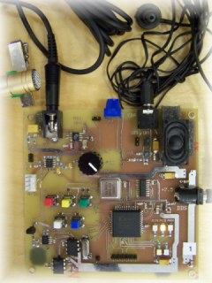
This system can be used as a demo board or lab test board for audio frequency processing circuits. It is typically hooked to microcontrollers that process audio signals and allows for easy testing and development.
Item Name: Audio Lab Board
Item Number: ALAB100
Price: $129.99
|
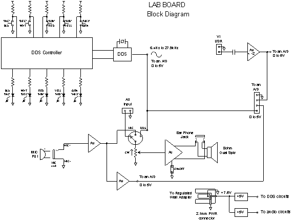
Circuits/items included on this board are (Refer to Figure 1 ):
- Audio amp - 0.7 Watt
- Speaker - 1.0 Watt max
- DDS oscillator – sinusoid generator – 6.4Hz to 27.9kHz
- Digital controller with push buttons and LEDs for the DDS
- Line level amplifier
- Microphone compression and signal conditioner
- Audio gain circuit and level shifter as a pre amp to an A/D with 5V input
- Power supply circuitry to support these functions

Figure 1: Block Diagram of Lab Board.
Applications
Audio front end for a MicroChip® or Atmel® microcontroller – process signal through A/D
Front end for computerized voice recognition
Microphone preamplifier/processor
Audio (voice) signal generator
Audio sine wave generator with a crystal reference clock
Audio pre-amp for FFT processing
Amplifier and speaker for external audio input
Digital Audio Experimentation board
Electronics Lab Learning tool for High School, Tech School, or College Engineering labs
Audio equipment frequency response tester
Robotics – sound/command recognition when used with a microcontroller
Included in the kit are:
- Populated and tested audio lab pcb.
- +7.5VDC regulated wall adapter
- Lapel microphone with a Projects Unlimited Incorporated (PUI) electret element connected to a standard 3.5mm plug. The user can also supply their own condenser microphone as the circuit will work with others.
- 8 ohm earphone attached to a 3.5mm plug.
- A printed user’s manual including complete schematic for pcb.
The board has a DDS (direct digital synthesizer) sinusoidal oscillator that its output signal is level shifted for an A/D input with a 5V input range. The frequency range of the sinusoidal signal from the DDS is between 6.4Hz and 27.9kHz.
It has a audio input (microphone input) that has its audio compressed and level shifted for an A/D input with a 0V to 5V input range. This same audio input can also be simultaneously processed by an on board audio amp and speaker.
The output signal of the DDS or an alternate user provided audio input signal can also be processed by this on board audio amp and speaker.
The board is powered by a 7.5VDC regulated wall adapter which is included in the kit. A 5V regulator is provided for the audio circuitry. Another 5V regulator is provided for the DDS sinusoid generator.
An extra op amp gain channel is provided to allow for gain of a user supplied input signal. The signal’s output is level shifted for an A/D input with a 5V input range. This op amp is for a line level signal. The gain from input to output is ~ -2. A measured result with both the input and output shown for this amplifier is given in Figure 5 .
Input signals with connectors to the board are the following:
- +7.5VDC power connector
- Microphone input
- Alternate audio input to audio amp
- Alternate signal sent to an op amp gain circuit
Output signals with connectors to the board are the following:
- Level shifted DDS (direct digital synthesizer) output for an A/D
- Compressed audio from microphone level shifted for an A/D
- Gained and level shifted user signal for an A/D
- Amplified audio signal from a microphone sent to an ear phone jack
Switches and jumpers:
- 3 position rotary switch selects
- DDS output sent to amp and speaker
- Microphone’s compressed audio signal sent to amp and speaker
- Alternate audio signal sent to amp and speaker
- On and off jumpers for audio amp
- Volume control effects sound output to speaker or ear phone
- 5 push buttons controlling the frequency for the output of the sinusoidal DDS oscillator
- Max push button (Green) – sets oscillator frequency to maximum
- Min push button (Red) – sets oscillator frequency to minimum
- Mid push button (Yellow) – set oscillator frequency to middle value
- Inc push button (Blue) – increments the oscillating frequency by a given step size – 2 speeds of incrementing determined by how long push button is held.
- Dec push button (White) – decrements the oscillating frequency by a given step size – 2 speeds of decrementing determined by how long push button is held.
- Push max and mid push buttons at same time and frequency goes to a value halfway between maximum and middle frequencies. Green and yellow LEDs are at dim level at the same time.
- Push min and mid push buttons at same time and frequency goes to a value halfway between minimum and middle frequencies. Red and Yellow LEDs are at a dim level at the same time.
- Push min and max push buttons at same time and frequency goes to the middle frequency value.
- Push inc and dec push buttons at the same time and the lamp test feature is enabled which lights all 5 LEDs at the same time.
LEDs:
- Max LED (Green) – DDS oscillator at maximum frequency
- Min LED (Red) – DDS oscillator at maximum frequency
- Mid LED (Yellow) – DDS oscillator at middle frequency
- Inc LED (Blue) – DDS oscillator is incremented in frequency. One blink on the
LED is one step up in frequency.
- Dec LED (White) – DDS oscillator is decremented in frequency. One blink on the LED is one step down in frequency.
|

